Getting Started with WinForms Diagram
This article shows how you can start using RadDiagram.
Adding Telerik Assemblies Using NuGet
To use RadDiagram when working with NuGet packages, install the Telerik.UI.for.WinForms.AllControls package. The package target framework version may vary.
If you don’t need all controls, you can instead install a more lightweight package targeting only RadDiagram: UI.for.WinForms.RadDiagram. This package has a dependency on UI.for.WinForms.Common, and UI.for.WinForms.Dock, that will be automatically installed when adding the RadDiagram NuGet.
Read more about NuGet installation in the Install using NuGet Packages article.
With the 2025 Q1 release, the Telerik UI for WinForms has a new licensing mechanism. You can learn more about it here.
Adding Assembly References Manually
When dragging and dropping a control from the Visual Studio (VS) Toolbox onto the Form Designer, VS automatically adds the necessary assemblies. However, if you're adding the control programmatically, you'll need to manually reference the following assemblies:
- Telerik.Licensing.Runtime
- Telerik.WinControls
- Telerik.WinControls.RadDiagram
- Telerik.WinControls.UI
- TelerikCommon
The Telerik UI for WinForms assemblies can be install by using one of the available installation approaches.
Defining the RadDiagram
Telerik RadDiagram are powerful diagramming framework that can bring to life your rich data-visualization scenarios.
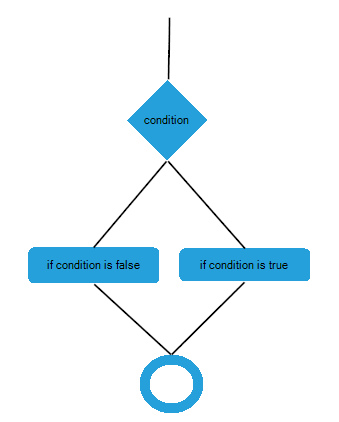
This tutorial will walk you through the main concepts and tools of RadDiagram while helping you to create the flow diagram of an "if-else" operator.
Graph Object Model
The graph object model is the main concept behind the diagramming framework. It contains the following three main objects:
graph - this is the structure that contains the RadDiagramShapes and RadDiagramConnections. In the Telerik Diagramming Framework the graph is represented by the RadDiagram class.
shape - the shape describes a node of a Graph that in the Telerik Diagramming Framework is represented by the RadDiagramShape class.
connection - the connection describes the edges of the graph and it is basically an object that connects zero, one or two shapes. In the Telerik Diagramming Framework the connection is represented by the RadDiagramConnection class.
The RadDiagram items are represented by the RadDiagramItem class. Therefore both RadDiagramConnection and RadDiagramShape classes derive from the RadDiagramItem class.
In order to populate RadDiagram with RadDiagramItems you can add RadDiagramShapes and RadDiagramConnections by using the Property Builder.
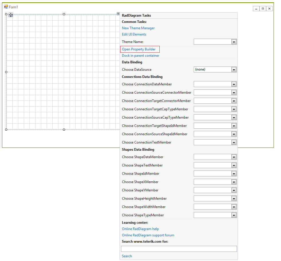
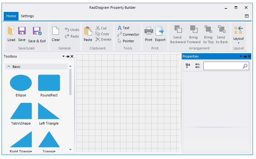
The Property Builder allows you to drag a shapes from the RadDiagramToolbox and drop it onto the RadDiagram surface. Afterwards, you can connect several shapes by using the connectors. The RadDiagramRibbonBar gives you a set of options to customize the diagram and save the changes as well.
In order to create a diagram describing the flow of an "if-else" operator, you will need 4 shapes - two will represent the statements, one will describe the condition and one will represent the final result of the operator.
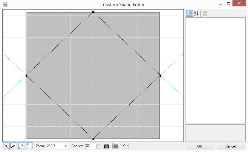
The RadDiagramShape exposes an ElementShape property that allows you to create a custom geometry or use predefined shape geometry.
Finally, you can connect all shapes using RadDiagramConnections.
See Also
Telerik UI for WinForms Learning Resources
- Telerik UI for WinForms Diagram Component
- Getting Started with Telerik UI for WinForms Components
- Telerik UI for WinForms Setup
- Telerik UI for WinForms Application Modernization
- Telerik UI for WinForms Visual Studio Templates
- Deploy Telerik UI for WinForms Applications
- Telerik UI for WinForms Virtual Classroom(Training Courses for Registered Users)
- Telerik UI for WinForms License Agreement)