Connections
This tutorial will walk you through the functionality and the main features of RadDiagramConnection.
Before proceeding with this topic, it is recommended to get familiar with the visual structure of the RadDiagram.
Overview
RadDiagramConnection is basically an object that connects zero, one or two shapes:

You can use its extensive API to configure its source and target points or shapes. You can choose from a list of predefined cap types thus customizing the start and end point of the connection to better fit in your application scenario. You can also control the type of a connection using the ConnectionType property, add a custom content and customize the overall look and feel of the items.
Configure the Source and Target of a Connection
The RadDiagramConnection class exposes the following properties that allow you to control the start and end points of a connection:
StartPoint/EndPoint - these properties are of type Telerik.Windows.Diagrams.Core.Point and they set or get the start/end point of a connection.
Source/Target - these properties get or set the source/target RadDiagramShape of a connection.
-
SourceConnectorPosition/TargetConnectorPosition - there are five predefined strings that you can use to define where to position the connectors of the connection:
Auto - use it if you want to automatically determine the start/end point of a connection. This option will allow the connection to dynamically determine which shape connector to be used as a start/end point. Based on the end point position, the SourceConnectorPosition will be set to the nearest shape connector. Alternatively, the TargetConnectorPosition will be set to the nearest shape connector, based on the start point position of the connection.
Left - use it to define the left connector of a shape as the source/target point of the connection
Top - use it to define the top connector of a shape as the source/target point of the connection
Right - use it to define the right connector of a shape as the source/target point of the connection
Bottom - use it to define the bottom connector of a shape as the source/target point of the connection
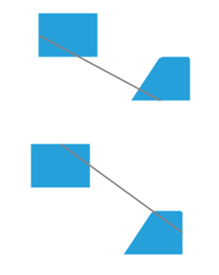
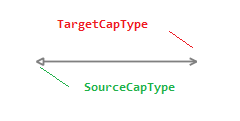
- SourceCapType/TargetCapType - both properties are an enumeration of type CapType that allow you to choose a cap from a set of predefined Cap types. For more detailed information, please, view the CapTypes section below.
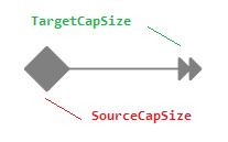
- SourceCapSize/TargetCapSize - these properties are of type Size and they get or set the size of the SourceCap/TargetCap.
Set Content
You can label a connection by setting its Content property.

connection1.Content = "connection label";
connection1.Content = "connection label"
Customize the Connection Appearance
You can easily customize the visual appearance of the RadDiagramConnection by using the following properties:
- BackColor: gets or sets the color that specifies how the RadDiagramConnection is painted.

connection1.BackColor = Color.Red;
connection1.BackColor = Color.Red
- StrokeThickness: gets or sets the width of the RadDiagramConnection outline.

connection1.StrokeThickness = 5;
connection1.StrokeThickness = 5
- ForeColor: gets or sets the color that specifies how the RadDiagramConnection's text is painted.

connection1.ForeColor = Color.Blue;
connection1.ForeColor = Color.Blue
- StrokeDashArray: gets or sets a collection of Double values that indicate the pattern of dashes and gaps that is used to outline the RadDiagramConnection.
connection1.StrokeDashArray = new Telerik.WinControls.UI.Diagrams.DoubleCollection(new List<float> { 2, 2, 2, 2 });
connection1.StrokeDashArray = New Telerik.WinControls.UI.Diagrams.DoubleCollection(New List(Of Single)() From { _
    2, _
    2, _
    2, _
    2 _
})

Connection Edit Mode
You can set the RadDiagramConnection in edit mode by using the IsInEditMode property. By default, when an item enters edit mode, the RadDiagramConnection.Content is displayed inside a TextBox control so that you can change its value.

Apart from setting the IsInEditMode property to true, you can also enter edit mode by pressing F2 or double-clicking on the connection. For more information please refer to the Editing article.
Connection Bridge
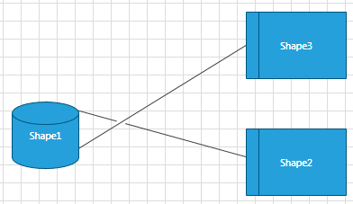
The connection bridge is essentially what you see when two connections collide. RadDiagram allows you to define what kind of bridge to display through the RadDiagram.ConnectionBridge property. It is an enumeration of type Telerik.Windows.Diagrams.Core.BridgeType that exposes the following members:
- None - there is no bridge to visualize the intersection of the connections
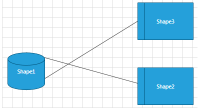
- Bow- a half circle is displayed to indicate the intersection of the connections

- Gap - a gap is displayed to indicate the intersection of the connections
Connection Selection State
The following properties allow you to track and control the selection state of a connection:
- IsSelected - gets or sets whether the connection is selected.
Connection ZIndex
You can get or set the z-order rendering behavior of the RadDiagramConnection through the ZIndex property.
Connection Bounds
You can get the bounds of a RadDiagramConnection through the Bounds property. It is of type Rect and it describes the width, height and location of the connection's bounds.