PathGeometry
In order to create a specific RadPath, you need to set a RadPathGeometry object to its Geometry property. The RadPathGeometry object exposes a Figures property which is a collection of RadPathFigures.
RadPathFigure
Each of the RadPathFigure objects is composed of one or several segments. These can be a RadArcSegment or a RadLineSegment. Adding several segments in combination with setting up the StartPoint of the RadPathFigure is enough for you to create the desired figure which should be added to the figures collection of the geometry.
Each line or arc segment you add to the path figure is drawn consequently - its starting point is the last point of the previous segment of the Segments collection of the PathFigure object. The first segment uses the StartPoint of the path figure as starting point.
RadArcSegment
The RadArcSegment represents an elliptical arc between two points. It exposes the following properties:
- Center: Defines the center point of the arc.
- Size: Sets the x- and y-diameter of the arc as a Size structure.
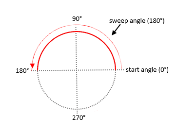
- StartAngle: Determines the angle from which the arc segment will start.
- SweepAngle: Specifies the length in degrees from the first to the second arc point. Positive angles are counter clockwise and negative angles clockwise.
The scheme below shows how StartAngle and SweepAngle are applied to the ArcSegment:
Here is a sample implementation of an RadArcSegment object:
<telerikPrimitives:RadPath x:Name="simpleArcPath"
                           StrokeThickness="4"
                           Stroke="#2EC262">
    <telerikCommon:RadPathGeometry>
        <telerikCommon:RadPathFigure StartPoint="1, 0.5">
            <telerikCommon:RadArcSegment Center = "0.5, 0.5"
                                         Size = "1, 1"
                                         StartAngle = "0"
                                         SweepAngle = "180" />
        </telerikCommon:RadPathFigure>
    </telerikCommon:RadPathGeometry>
 </telerikPrimitives:RadPath>
RadLineSegment
Creates a line between two points in a RadPathFigure. The starting point of the line is defined either by the previous segment's end point or by the StartPoint of the PathFigure object. The end point is defined by the Point property of the LineSegment object.
The thickness and the color of the line are determined by the StrokeThickness and Stroke properties of the Path object this line figure is added to.
Check below a simple example of how to create a line PathFigure:
<telerikPrimitives:RadPath x:Name="simpleLinePath"
                           StrokeThickness="4"
                           Stroke="#2EC262">
    <telerikCommon:RadPathGeometry>
        <telerikCommon:RadPathFigure StartPoint="0.8, 0.1">
            <telerikCommon:RadLineSegment Point="0.1, 0.8" />
        </telerikCommon:RadPathFigure>
    </telerikCommon:RadPathGeometry>
</telerikPrimitives:RadPath>
Example
The following example shows how to create a more complex RadPathGeometry object and add a line with curved edges to its Figures collection.
First you should define the RadPath figure:
<telerikPrimitives:RadPath x:Name="customLinePath"
                           Grid.Row="0"
                           StrokeThickness="0"
                           Fill="#3DBAFE"/>
And then you set its Geometry to have the following structure:
RadPathFigure customLine = new RadPathFigure();
customLine.StartPoint = new Point(0.8, 0.1);
customLine.Segments.Add(new RadLineSegment(new Point(0.1, 0.8)));

customLine.Segments.Add(new RadArcSegment() { Center = new Point(0.125, 0.825), StartAngle = 135, SweepAngle = 180, Size = new Size(0.070710678, 0.070710678) });
customLine.Segments.Add(new RadLineSegment(new Point(0.85, 0.15)));
customLine.Segments.Add(new RadArcSegment() { Center = new Point(0.825, 0.125), StartAngle = 315, SweepAngle = 180, Size = new Size(0.070710678, 0.070710678) });

RadPathGeometry geometry = new RadPathGeometry();
geometry.Figures.Add(customLine);
customLinePath.Geometry = geometry;
Check the screenshot below which shows the result after creating the three Paths: