Connectors
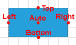
The RadDiagramShape and RadDiagramContainerShape visuals have 5 default connectors - Top, Right, Bottom, Left and Auto. Those are the predefined points where you can connect a RadDiagramConnection to the shape.
-
Top: The connector point positioned in the middle of the top border of a shape
-
Bottom: The connector point positioned in the middle of the bottom border of a shape
- Right: The connector point positioned in the middle of the right border of a shape
- Left: The connector point positioned in the middle of the left border of a shape
-
Auto: The connector positioned at the center of a shape. If you attach a RadDiagramConnection to this point, the connector point of the connection will dynamically change based on the shortest path to the shape.
Get the Connectors
All connector points of a shape can be accessed through the Connectors property of RadDiagramShape. It is a collection of RadDiagramConnector items. Each item represents a RadDiagramShape connector and can give you information about the coordinates of each connector point, its position and if the connector is active. A connector is active when the connection tool activates it in order to prepare it to start drawing a connection.
Using Gliding Connectors
The gliding connectors feature says to a shape that it doesn't have any explicitly pisitioned connectors. This allows a connection to glide through the edges of the shape.
To enable the gliding connectors you can set the UseGlidingConnector property of RadDiagramShape to True.
This feature comes with a set of predefined shape forms determining the form of edges through which a gliding connection can slide. These shapes are described by the GlidingStyle property, which is a GlidingStyle enumeration exposing the following members:
Rectangle: The connections attached to a gliding connector will glide along a rectangle with dimensions equal to the bounds of the shape. This is the default value.
Ellipse: The connections attached to a gliding connector will glide along an ellipse with dimensions equal to the bounds of the shape.
Diamond: The connections attached to a gliding connector will glide along a rhombus (diamond polygon) with dimensions equal to the bounds of the shape.
RightTriangle: The connections attached to a gliding connector will glide along a right triangle with dimensions equal to the bounds of the shape.
Triangle: The connections attached to a gliding connector will glide along a triangle with dimensions equal to the bounds of the shape.
Hiding the Default Connectors
To hide the default connectors you can set the UseDefaultConnectors property of the RadDiagramShape and RadDiagramContainerShape to False.
Using Custom Connectors
You can see how to use custom connectors in the Custom Connectors article.
Additionally, you can customize the default appearance of the connector points through the ConnectorStyle property of RadDiagramShape which allows you to apply a custom style on them.
Undo Command When Using Custom Connectors
The diagram doesn't support undo custom type connectors when Undo command is executed. Executing the command will create the connectors of type RadDiagramConnector by default. To Undo custom connectors, your custom class needs to implement the ICloneable interface. Then you can implement its Clone() method and return your custom type.
Example 1: Undo Custom Connectors
public class CustomConnector : RadDiagramConnector, ICloneable
{
    object ICloneable.Clone()
    {
        CustomConnector diagramConnector = new CustomConnector();
        diagramConnector.Name = this.Name;
        diagramConnector.Offset = this.Offset;
        return diagramConnector;
    }
}