Routing
Routing is a mechanism using algorithms to make sure that the connections don't cross each other while building links/paths between the shapes.
Default Routing
Routing in RadDiagram is only available if the RadDiagram.RouteConnections property is set to true. Please note that its default value is False and you need to explicitly declare you want to enable the routing features.
Figure 1: Routing
The routing algorithm can be parametrized using the DiagramConstants.RoutingGridSize constant that has a default value of 40 units. This value indicates the size of the cells of the underlying grid used by the algorithm:
A bigger value will decrease the time to compute the optimal path and will diminish the possible wiggling of the connection path due to obstacles (other shapes). On the other hand, a bigger value will not necessarily lead to an optimal solution in certain circumstances. That is, if your diagram involves a lot of shapes and a high complexity a bigger RoutingGridSize will not find a path through the maze of shapes.
A smaller value will increase the time tom compute the optimal path and increase the set of possible solutions for the path constraints. On the other hand, a small value leads usually to a lot of stairs/wiggling in the connection's path.
OrgTreeRouter
The OrgTreeRouter is a LayoutType - based router that performs a hierarchical routing between parent and child shape. When a shape is being dragged, it removes only the crossings between the connection and its source and target shapes. It should be used when following conditions are satisfied:
The IsConnectorsManipulationEnabled is set to false.
The LayoutType is among the following 5 - TipOverTree, TreeDown, TreeUp, TreeLeft, TreeRight.
In order to use the OrgTreeRouter, you have to instantiate an OrgTreeRouter object and set it as current Router of the RadDiagram via the RoutingService:
Telerik.Windows.Diagrams.Core.OrgTreeRouter router = new Telerik.Windows.Diagrams.Core.OrgTreeRouter()
{
    TreeLayoutType = Telerik.Windows.Diagrams.Core.TreeLayoutType.TreeDown,
    ConnectionOuterSpacing = 20,
};
this.radDiagram1.RoutingService.Router = router;
Dim router As New Telerik.Windows.Diagrams.Core.OrgTreeRouter() With { _
    .TreeLayoutType = Telerik.Windows.Diagrams.Core.TreeLayoutType.TreeDown, _
    .ConnectionOuterSpacing = 20 _
}
Me.RadDiagram1.RoutingService.Router = router
The TreeLayoutType points to the type of Layout you wish to use. The routing logic is based on this LayoutType. The ConnectionOuterSpacing is the minimum margin between the Parent/Child Shape and the connection.
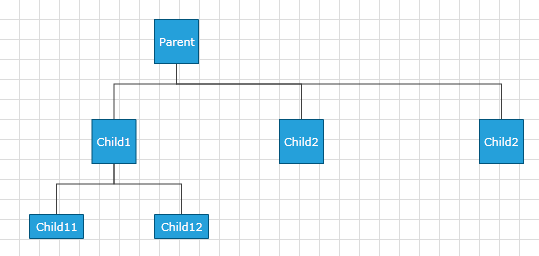
Below you can see these shapes after TreeDown Layout operation performed on the RadDiagram.
Figure 2: TreeDown
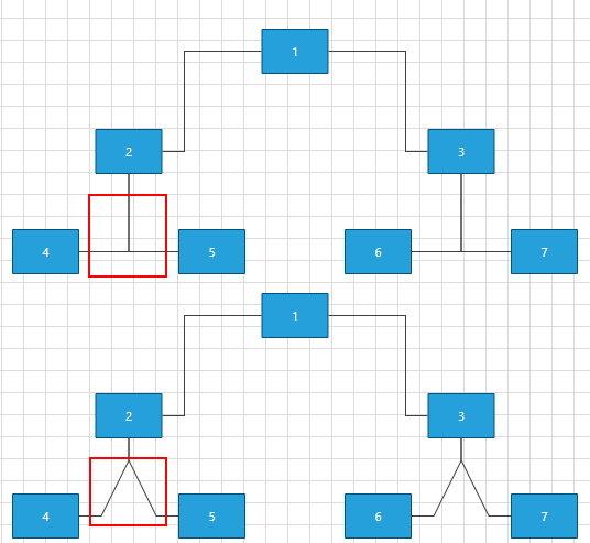
OrgTreeRouter: TipOverTreeRouter
When the TreeLayoutType is set to TipOverTree, the OrgTreeRouter uses a special kind of router - the TipOverTreeRouter. It produces best visual results when a custom connectors are added in the bottom-left part of the shapes.
Here is a sample code snippet demonstrating how to create and configure TreeLayoutSettings and create and assign a Router to be the default one.
Telerik.Windows.Diagrams.Core.TreeLayoutSettings settings = new Telerik.Windows.Diagrams.Core.TreeLayoutSettings()
{
    TreeLayoutType = Telerik.Windows.Diagrams.Core.TreeLayoutType.TipOverTree,
    UnderneathVerticalSeparation = 50,
    VerticalDistance = 50,
    UnderneathHorizontalOffset = 50,
    UnderneathVerticalTopOffset = 50
};
settings.Roots.Add(this.radDiagram1.Shapes[0]);
Telerik.Windows.Diagrams.Core.OrgTreeRouter router = new Telerik.Windows.Diagrams.Core.OrgTreeRouter()
{
    TreeLayoutType = Telerik.Windows.Diagrams.Core.TreeLayoutType.TipOverTree,
    ConnectionOuterSpacing = 10
};
this.radDiagram1.RoutingService.Router = router;
this.radDiagram1.SetLayout(Telerik.Windows.Diagrams.Core.LayoutType.Tree, settings);
Dim settings As New Telerik.Windows.Diagrams.Core.TreeLayoutSettings() With { _
    .TreeLayoutType = Telerik.Windows.Diagrams.Core.TreeLayoutType.TipOverTree, _
    .UnderneathVerticalSeparation = 50, _
    .VerticalDistance = 50, _
    .UnderneathHorizontalOffset = 50, _
    .UnderneathVerticalTopOffset = 50 _
}
settings.Roots.Add(Me.RadDiagram1.Shapes(0))
Dim router As New Telerik.Windows.Diagrams.Core.OrgTreeRouter() With { _
    .TreeLayoutType = Telerik.Windows.Diagrams.Core.TreeLayoutType.TipOverTree, _
    .ConnectionOuterSpacing = 10 _
}
Me.RadDiagram1.RoutingService.Router = router
Me.RadDiagram1.SetLayout(Telerik.Windows.Diagrams.Core.LayoutType.Tree, settings)
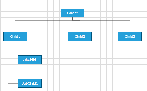
The following screenshot illustrates the result:
Figure 3: TipOverTreeRouter
AStarRouter
As the name suggests, this is a connection router that uses a version of the A* search algorithm to find the best route between two points. There are several ways to parameterize the algorithm:
- Using Diagram Constants
* DiagramConstants.RoutingGridSize - of type double and gets or sets the routing grid size.
Figure 4: RoutingGridSize
* DiagramConstants.RouterInflationValue - of type double and gets or sets the size of the restricted area around the shapes.
- Using properties of the router
* AvoidShapes - boolean property controlling the logic that makes the connections go around the shapes. This property is false by default.
Figure 5: AvoidShapes
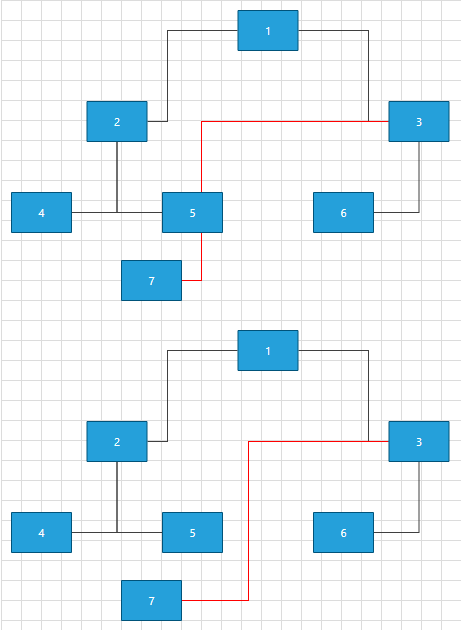
* WallOptimization- boolean property controlling router optimization logic. If you set this property to true the router will try to optimize some of the steps so that there are the least corners.
With the R2 2021 SP1 version of Telerik UI for WinForms, several properties were created which can be used to further modify the algorithm for the routing connections. In order the changes to be applied to the algorithm, the AvoidConnectionOverlap property of the AStarRouter need to be set to true.
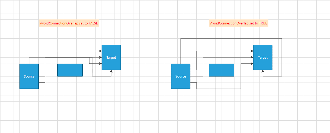
- AvoidConnectionOverlap: Boolean property that gets or sets a value which indicates whether the routing algorithm should try to minimize connection overlaps. The default value is false.
Setting AvoidConnectionOverlap property
SegmentOverlapPenalty: A property of type double that indicates the penalty of a given path when it overlaps an existing diagram connection. Decreasing the value close to 0, the connections' behavior will become very close to when AvoidConnectionOverlap is set to false. The connections will start to cross each other. At another hand increasing this property, the connections might start to cross a given shape (avoiding connection will be with higher priority than avoiding a shape). There is no strict number when one is more important than the other. It dependents on the concrete scenario. The default value is 0.5.
ShapeCrossPenalty: A property of type double that indicates the penalty of a given path when it overlaps an existing diagram connection. The default value is 1.
SegmentOverlapDistance: A property of type double that gets or sets the surrounding area of a segment in which an overlap is detected. This property require AvoidConnectionOverlap to be set to True.
Using virtual methods
If the customization provided by these properties does not cover your requirements, you can create your custom router deriving from ours. This will allow you to customize the algorithm by overriding the following methods:
* GetSiblingNodes - this method receives the current state and the end target and should return the next possible nodes
The order in which the steps are returned is important - if you have two steps with the same price we'll choose the first one.
* CalculateWallPenalty - this method calculates the penalty for the node that we give it. By default if the node is inside a shape we return the penaltyBaseValue which is the heuristic distance to the endpoint.
* CalculateBendAlteration - this method calculates the bend alteration. By default the result value can be positive - a penalty for changing the direction or negative - a bonus for keeping the direction.
If the source and target positions of your connections are Auto this router will adjust them so that the path is minimal.
InflatedRectRouter
The InflatedRectRouter is a simple connection router whose goal is to create a route with least bends. This router doesn't try go around shapes except the start and end shape.
Custom Router
In the following section we will create a custom Router. This way we will be able to set the routing points of our Polyline Connections.
Let's first create some items:
RadDiagramShape shapeA = new RadDiagramShape()
{
    Text = "ShapeA",
    ElementShape = new RoundRectShape(4),
    BackColor = Color.CadetBlue
};
shapeA.Position = new Telerik.Windows.Diagrams.Core.Point(100, 100);
this.radDiagram1.Items.Add(shapeA);

RadDiagramShape shapeB = new RadDiagramShape()
{
    Text = "ShapeB",
    ElementShape = new RoundRectShape(4),
    BackColor = Color.CadetBlue
};
shapeB.Position = new Telerik.Windows.Diagrams.Core.Point(300, 100);
this.radDiagram1.Items.Add(shapeB);

RadDiagramConnection connection = new RadDiagramConnection()
{
    Source = shapeA,
    Target = shapeB
};
this.radDiagram1.Items.Add(connection);
Dim shapeA As New RadDiagramShape() With { _
    .Text = "ShapeA", _
    .ElementShape = New RoundRectShape(4), _
    .BackColor = Color.CadetBlue _
}
shapeA.Position = New Telerik.Windows.Diagrams.Core.Point(100, 100)
Me.RadDiagram1.Items.Add(shapeA)
Dim shapeB As New RadDiagramShape() With { _
    .Text = "ShapeB", _
    .ElementShape = New RoundRectShape(4), _
    .BackColor = Color.CadetBlue _
}
shapeB.Position = New Telerik.Windows.Diagrams.Core.Point(300, 100)
Me.RadDiagram1.Items.Add(shapeB)
Dim connection As New RadDiagramConnection() With { _
    .Source = shapeA, _
    .Target = shapeB _
}
Me.RadDiagram1.Items.Add(connection)
Now we have to create class that implements the IRouter interface and override the GetRoutePoints() method:
public class CustomRouter : Telerik.Windows.Diagrams.Core.IRouter
{
    public System.Collections.Generic.IList<Telerik.Windows.Diagrams.Core.Point> GetRoutePoints(Telerik.Windows.Diagrams.Core.IConnection connection, bool showLastLine)
    {
        List<Telerik.Windows.Diagrams.Core.Point> pointList = new List<Telerik.Windows.Diagrams.Core.Point>();
        Telerik.Windows.Diagrams.Core.Point start = connection.StartPoint;
        Telerik.Windows.Diagrams.Core.Point end = connection.EndPoint;

        pointList.Add(new Telerik.Windows.Diagrams.Core.Point(start.X + (end.X - start.X) * 0.45, start.Y));
        pointList.Add(new Telerik.Windows.Diagrams.Core.Point((start.X + end.X) / 2, (start.Y + end.Y) / 2 - 50));
        pointList.Add(new Telerik.Windows.Diagrams.Core.Point((start.X + end.X) / 2, (start.Y + end.Y) / 2 + 50));
        pointList.Add(new Telerik.Windows.Diagrams.Core.Point(start.X + (end.X - start.X) * 0.55, end.Y));

        return pointList;
    }
}
Public Class CustomRouter
Implements Telerik.Windows.Diagrams.Core.IRouter
    Public Function GetRoutePoints1(connection As Telerik.Windows.Diagrams.Core.IConnection, showLastLine As Boolean) As IList(Of Telerik.Windows.Diagrams.Core.Point) Implements Telerik.Windows.Diagrams.Core.IRouter.GetRoutePoints
        Dim pointList As New List(Of Telerik.Windows.Diagrams.Core.Point)()
        Dim start As Telerik.Windows.Diagrams.Core.Point = connection.StartPoint
        Dim [end] As Telerik.Windows.Diagrams.Core.Point = connection.EndPoint
        pointList.Add(New Telerik.Windows.Diagrams.Core.Point(start.X + ([end].X - start.X) * 0.45, start.Y))
        pointList.Add(New Telerik.Windows.Diagrams.Core.Point((start.X + [end].X) / 2, (start.Y + [end].Y) / 2 - 50))
        pointList.Add(New Telerik.Windows.Diagrams.Core.Point((start.X + [end].X) / 2, (start.Y + [end].Y) / 2 + 50))
        pointList.Add(New Telerik.Windows.Diagrams.Core.Point(start.X + ([end].X - start.X) * 0.55, [end].Y))
        Return pointList
    End Function
End Class
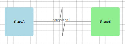
Please note that we only have to add in the list the route points, no need to add the start and the end point of the connection.
The final step is to make our router the current one of the RadDiagram. This is done via Diagram's Routing Service:
this.radDiagram1.RouteConnections = true;
this.radDiagram1.RoutingService.Router = new CustomRouter();
Me.RadDiagram1.RouteConnections = True
Me.RadDiagram1.RoutingService.Router = New CustomRouter()
Figure 6: Custom Router